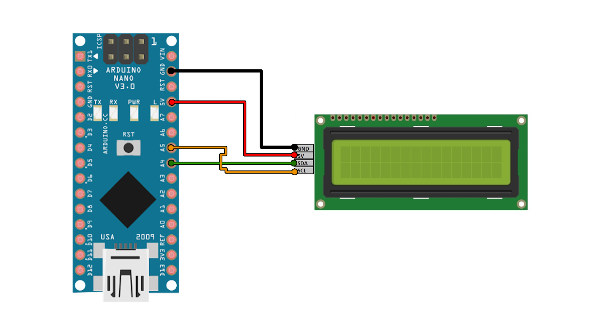

- Coding lcd arduino how to#
- Coding lcd arduino software#
- Coding lcd arduino code#
- Coding lcd arduino simulator#
Coding lcd arduino software#
Coding lcd arduino code#
Posted in Arduino Hacks Tagged arduino, code, code hacks, hd44780, menu, menu code Post navigation If you find text menus too archaic for your purposes, though, be sure to sound off with your favourite solutions in the comments. It’s the sort of thing you might use if you’d built a do-everything Arduino handheld device, as we’ve seen built before. However, modifying the code to use an alternate button scheme would be simple for those eager to tweak things to their liking.įor the absolute beginner to programming, it’s a great way to put together a simple interface for your microcontroller projects. This suits the commonly available Arduino shields which combine a 16×2 character LCD with a set of four tactile buttons in a cross formation. By default, it’s set up to work with left and right function buttons, with up and down buttons to toggle through the menu’s various entries. It allows the user to define a certain number of menu items, along with button labels and functions to be executed with button presses. The menu code is simple to modify and implement. If you’re using such a device, you might want to implement a simple menu system, and in that case, has you covered. However, for many purposes, the humble HD44780 character LCD does the job just fine. OLEDs and graphic LCDs abound, while e-ink devices tempt the user with their clean look and low energy consumption. Here's some useful info on getting that PCB made.These days, there’s a huge variety of screens on the market for use with microcontrollers. The project has a "Download Gerber" button that will get you the files necessary to give to a printed circuit board (PCB) manufacturer to have a custom printed circuit board made. If you are so inclined, you can also make a circuit board to nicely connect your electronics to the Arduino. There's also a full-featured debugger where you can step through the program line-by-line and see what's going on!


You can then edit the source code and try out changes right there. If you want to make any changes to the game, or explore what's going on, you can copy the virtual circuit using the "Duplicate Project" button. You can actually play the game right in your browser without ever having to put together any actual electronics ("Oh, now you tell me"). Here's the virtual circuit for the Arduino LCD game.

I actually had the game fully working and tested before ever taking the Arduino out of the kit.
Coding lcd arduino simulator#
I developed this game entirely using the very cool (FREE!) online electronics simulator Tinkercad Circuits.
Coding lcd arduino how to#
If you want to change the way the game works, or make a cool printed circuit board for this project that plugs directly onto the Arduino and replaces of all those messy wires, here's how to get started. Connect the other pin at the top of the button to pin 2 of the Arduino.Īt this point you have everything working, so what more is there to do? Connect one of the top two pins of the button to the black row at the top of the breadboard using a short hookup wire. Plug the pushbutton somewhere to the left of the LCD screen, straddling the channel running along the center of the breadboard (see picture above). Connect V0 to Arduino pin 12 (or to black row at top of breadboard).Connect R/W to Arduino pin 10 (or to black row at top of breadboard).Use longer hookup wires to make the remainder of the connections: Similarly, connect VCC (pin 2) to the red row at the top with a short hookup wire.īend the wire leads of the 220 Ω resistor (red-red-brown colored bands) and connect it between LED+ and the red row at the top of the breadboard. Using short hookup wires, connect GND and LED- (pins 1 and 16) to the black row at the top. All of the electronic signals that power and control the LCD go through this header. Plug this into the breadboard as shown in the picture. The LCD (Liquid Crystal Display) module has a 16-pin male header on the underside. Use a long hookup wire to connect the GND signal to the far left of the black (or blue on some breadboards) row at the top of the breadboard. Use a long hookup wire to connect the 5V signal on the Arduino to the far left of the red row at the top of the breadboard. That will happen in a later step when it is time to program it and try the game out. The parts needed are shown in the picture above.


 0 kommentar(er)
